§ 1066.625 Flow meter calibration calculations.
This section describes the calculations for calibrating various flow meters based on mass flow rates. Calibrate your flow meter according to 40 CFR 1065.640 instead if you calculate emissions based on molar flow rates.
(a) PDP calibration. Perform the following steps to calibrate a PDP flow meter:
(1) Calculate PDP volume pumped per revolution, Vrev, for each restrictor position from the mean values determined in § 1066.140:

Where:
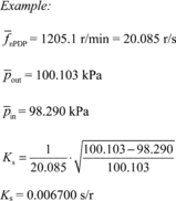
Example:

(2) Calculate a PDP slip correction factor, Ks for each restrictor position from the mean values determined in § 1066.140:

Where:

(3) Perform a least-squares regression of Vrev, versus Ks, by calculating slope, a1, and intercept, a0, as described in 40 CFR 1065.602.
(4) Repeat the procedure in paragraphs (a)(1) through (3) of this section for every speed that you run your PDP.
(5) The following example illustrates a range of typical values for different PDP speeds:
Table 1 of § 1066.625—Example of PDP Calibration Data
| f ~nPDP (revolution/s) | a1 (m 3/s) | a0 (m 3/revolution) |
|---|---|---|
| 12.6 | 0.841 | 0.056 |
| 16.5 | 0.831 | −0.013 |
| 20.9 | 0.809 | 0.028 |
| 23.4 | 0.788 | −0.061 |
(6) For each speed at which you operate the PDP, use the appropriate regression equation from this paragraph (a) to calculate flow rate during emission testing as described in § 1066.630.
(b) SSV calibration. The equations governing SSV flow assume one-dimensional isentropic inviscid flow of an ideal gas. Paragraph (b)(2)(iv) of this section describes other assumptions that may apply. If good engineering judgment dictates that you account for gas compressibility, you may either use an appropriate equation of state to determine values of Z as a function of measured pressure and temperature, or you may develop your own calibration equations based on good engineering judgment. Note that the equation for the flow coefficient, Cf, is based on the ideal gas assumption that the isentropic exponent, g, is equal to the ratio of specific heats, Cp/Cv. If good engineering judgment dictates using a real gas isentropic exponent, you may either use an appropriate equation of state to determine values of γ as a function of measured pressure and temperature, or you may develop your own calibration equations based on good engineering judgment.